
● Built-in PID parameter adjustment function enables the motor to better meet the application of different types of loads.
● Built-in field weakening control algorithm reduces the magnetic field characteristics of the motor at high speed and maintains power.
● Built-in current vector control function makes the motor have servo current characteristics and low heat generation.
● Built-in micro-step instruction algorithm, so that the motor speed stage to maintain stable, low vibration.
● Built-in 4000pulse resolution encoder feedback, so that the motor accuracy, never lost step.
| Drive function | Instructions |
|---|---|
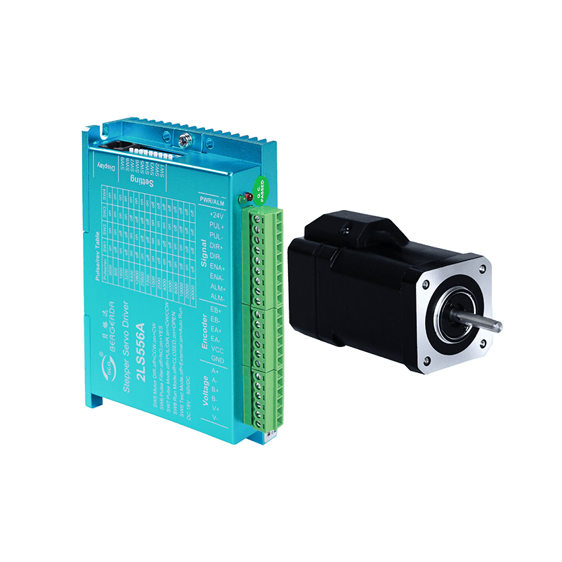
| Command pulse form | The standard LS series driver signal interface is in pulse form and can accept two types of pulse command signals; 1. Pulse & Direction (PUL + DIR); 2. Double Pulse (CW + CCW); |
| output signal | It can be set to alarm output by parameter, positioning completion output, brake output; default is alarm output and positioning completion output. |
| Control algorithm is optional | The leading space vector servo control algorithm and the traditional advance angle control algorithm are optional, and the user can arbitrarily select according to the occasion. |
| External display | The DISPlay interface can be connected to the display for easy setting of parameters and observation of operating conditions. |
| Wide voltage range on Signal terminal | Pulse, direction and enable signal input interface voltage 5V and 24V separate terminals, simple wiring, strong anti-interference ability |
| Seven status LED displays | The LS series driver has two operating states and five fault LED indication functions, allowing the user to clearly confirm the status of the driver. |
| Motor frame | Motor model | Rated torque | Encoder line specification | Supporting drive model |
|---|---|---|---|---|
| 42 | 42BG04-EC | 0.48NM | lead line 3 meters | 2LS556A |
| 42 | 42BG06-EC | 0.72NM | lead line 3 meters | 2LS556A |
| 57 | 57BG10-EC | 1.0NM | lead line 3 meters | 2LS556A |
| 57 | 57BG20-EC | 2.0NM | lead line 3 meters | 2LS556A |
| 60 | 60BG30-EC | 3.0NM | lead line 3 meters | 2LS556A |
| 86 | 86BG40-EC | 4.5NM | lead line 3 meters | 2LS860H |
| 86 | 86BG80-EC | 8.5NM | lead line 3 meters | 2LS860H |
| 86 | 86BG120-EC | 12NM | lead line 3 meters | 2LS860H |
Note:
1. Standard model motor directly out of the 3 meter encoder line
2. Non-standard model closed-loop motor suffix plus L such as :57BG20-ECL(body outlet length 500mm) extension cord with other models:L-030

| Parameter No. | definition | function | Factory default |
|---|---|---|---|
| 0 | Maximum current value | Set the maximum output current of the driver | 72 |
| 1 | Light load current ratio | Set the operating current to maximum current ratio at light load. When the load can be driven, the lower setting is beneficial to reduce the heating of the motor. | 50 |
| 2 | Input signal logic inversion | Input inversion | 0 |
| 3 | Output signal logic inversion | 1: Output port 1 logic inversion 2: Output port 2 logic inversion | 0 |
| 4 | Output port 1 function definition (corresponding to silk screen pend) | 0: Alarm 1: Brake 2: Positioning completed | 2 |
| 5 | Output port 2 function definition | 0: Alarm 1: Brake 2: Positioning completed | 0 |
| 6 | Positioning completion range setting | The position deviation is lower than the set value output positioning completion signal | 20 |
| 7 | Number of encoder lines | Encoder one revolution pulse number | 1000 |
| 8 | Position error alarm setting | When the position deviation is higher than the set value, the drive output position is out of tolerance alarm | 4000 |
| 9 | Pulse command smoothing | When the input pulse frequency is low, the setting is larger, which makes the motor run more smoothly (the dialing S6 switch can be turned off) | 500 |
| 10 | Drive proportional gain | When the input pulse frequency is low,the setting is larger, which makes the motor run more smoothly (the dialing S6 switch can be turned off) | 80 |
| 11 | Drive proportional integral | 15 | |
| 12 | Position ac/deceleration coefficient | 0:No ac/deceleration.For other values,the smaller the value ,the slower the ac/deceleration | |
| 14 | Off enable delay time | After off the enable, delay the brake time to ensure the brake is applied after the motor is excitation | 100 |
| 15 | Motor power line phase modulation | After motor power phase modulation, normal control can be realized without changing the phase sequence of the encoder. | 0 |
| 20 | Alarm record 0 | Last alarm record | 0 |
| 21 | Alarm record 1 | Second last alarm record | 0 |
| 27 | Alarm record 7 | Countdown to the eighth alarm record | 0 |
| 30 | Drive version | 106 | |
| 31 | Motor code | 42BG04-EC:4 42BG06-EC:3 57BG20-EC:0 86BG80-EC:6 |
| No. | content | definition |
|---|---|---|
| 1 | r | Rotating speed |
| 2 | i | Current |
| 3 | c | Command position |
| 4 | E | Encoder wheel position |
| 5 | d | Position deviation |
| 6 | d . | Position deviation after acceleration and deceleration |
| 7 | IO | The status of the input and output signals is displayed from right to left. The upper part of the digital tube is on and off: d1: enable d2: direction d3: pulse d5: output 1 d6: output 2 |
| 8 | EE-OP | Press Enter to restore the default value, it takes a while |
| 9 | PA | Display and modify individual parameters |