
Based on the platform of 32-bit ARM processing chip, the magnetic field orientation and high-speed flux-weakening algorithm in the servo driver are designed to achieve excellent performance.
The built-in vector control design and servo demodulation function of the driver, combined with the feed back of the closed-loop motor encoder, make the stepping servo system have the features of low noise, low heating.no lost steps and higher application speed, and can improve the intelligent equipment system performance in all directions.
♦ Pulse mode: single pulse/ CW/CCW pulse
♦ Signal level: 5V/24V separate wiring, simple and practical, strong anti-interference ability.device where the user desires high rotation speed and high torque.
♦ Typical applications lock screw machine, servo dispensing machine, stripping machine, labeling machine,medical detector, electronic assembly equipment etc. The application effect is particularly good in a device where the user desires high rotation speed and high torque.
| Drive function | Operating Instructions |
|---|---|
| Microstep subdivision setting | SW1-SW4 four dial codes are used to select a total of 16 files of microsteps. When the user sets the subdivision, electric motion should be stopped first. For detailed microstep subdivision settings, please see the drive panel description. |
| Running direction setting | SW5 is used to select the initial direction of rotation of the motor. It is necessary to power off and restart the drive to make effect. |
| Pulse smoothing selection | Sw6 is used to select whether to enable the internal S-type command smoothing function. Turn on this function when ON to make the driver input pulse signal smoother. It is necessary to power off and restarts the drive to make effect. |
| Pulse mode selection | Sw7 is used to select the input pulse mode, off is the pulse & direction, and on is CW/CCW pulse. It is necessary to power off and restart the drive to make effect. |
| Open/closed loop selection | Sw8 is used to select the control mode, off is the closed loop mode, and on is the open loop mode. |
| Pulse control / automatic operation selection | Sw9 pulse control / automatic operation select off: Receive external pulse control, on drive automatically with 20RPM automatic forward and reverse, can be used to test the motor and drive |
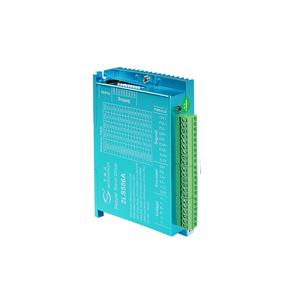
| Signal interface | PUL+ and PUL- are the positive and negative ends of the control pulse signal; DIR+ and DIR- are the positive and negative ends of the direction signal; ENA+ and ENA- are the positive and negative ends of the enable signal; ALM+ and ALM- are the Positive and negative ends of alarm output signals. The ALM port can also be configured for brake output or positioning completion. |
| Encoder interface | EB+ and EB- are encoder B direction signals; EA+ and EA- are encoder A direction signals; VCC and GND are encoder power interfaces.' |
| Motor interface | A+, A-, B+, B- are the stepping servo motor winding interfaces, which must be linked with the motor identification color and cannot be exchanged.If the phase sequence of the encoder and motor power line is reversed, you can change the parameter resolution. |
| Power interface | V+, V- are the positive and negative terminals of the input DC power supply, 2LS556A operating voltage range 24-50 VDC, voltage power greater than 150W. |
| LED | The driver has two indicators, red and green. The green light is the power indicator. The green light flashes after the driver is powered on. The red light is the fault indicator. The red light flickers when there is a fault in the gear and the encoder is misaligned. After the fault is cleared, the red light goes out. When an alarm occurs on the drive, it must be powered on again to clear the fault. |
| Installation Notes | Dimensions: 118 * 75.5 * 33 mm, mounting hole spacing 112. Can be horizontal or vertical installation, but it should be close to the metal cabinet for better cooling |
| LED status | Drive status | |
|---|---|---|
| Green light | Drive is not enabled | |
| Green flashing | The driver is working properly(Pulse flashing faster) | |
| 1green、1red | Drive overcurrent | |
| 1 green、2 red | Encoder counter or no encoder | |
| 1 green、3 red | Location out of tolerance | |
| 1 green、5 red | ADC hardware error | |

| Steps / Turn | SW1 | SW2 | SW3 | SW4 |
|---|---|---|---|---|
| 3600 | on | on | on | on |
| 800 | off | on | on | on |
| 1600 | on | off | on | on |
| 3200 | off | off | on | on |
| 6400 | on | on | off | on |
| 12800 | off | on | off | on |
| 25600 | on | off | off | on |
| 7200 | off | off | off | on |
| 1000 | on | on | on | off |
| 2000 | off | on | on | off |
| 4000 | on | off | on | off |
| 5000 | off | off | on | off |
| 8000 | on | on | off | off |
| 10000 | off | on | off | off |
| 20000 | on | off | off | off |
| 40000 | off | off | off | off |