
Based on ARM's new 32-bit DSP processing chip platform, the internal PID current control algorithm design, with excellent performance. The built-in micro-segmentation technology and the automatic tuning function of the power-on parameter make the driver have the characteristics of low noise,low vibration, low heat generation and high-speed high torque output In addition, the patented three-phase demodulation algorithm can give full play to the low-speed resonance and small torque ripple characteristics of the phase stepping motor, and can be well adapted to applications requiring higher stability.
♦ Pulse mode: single pulse/ CW/CCW pulse
♦ Signal level:5V/24V separate wiring, simple and practical strong anti-interference ability
♦ Typical applications: potting machines, engraving machines, cutting machines, laser equipment,CNC machine tools, automatic equipment and so on. The application effect is particularly good in a device where the user desires high speed and small noise.
| Drive function | Operating Instructions |
|---|---|
| Microstep subdivision setting | SW5-SW8 four dial codes are used to select a total of 16 files of microsteps. When the user sets the subdivision, electric motion should be stopped first. For detailed microstep subdivision settings, please see the drive panel description. |
| Output current setting | SW1-SW3 three dial switches are used to select a total of 8 output currents. For the specific output current setting, please see the driver panel description. |
| Pulse smoothing filter | The SW4 dial code is used to select the pulse smoothing function of the drive, the off means the off function, and on means the function is turned on |
| Pulse form selection | SW9 dial code is used to select the pulse form, OFF: pulse + direction ON : CW/CCW |
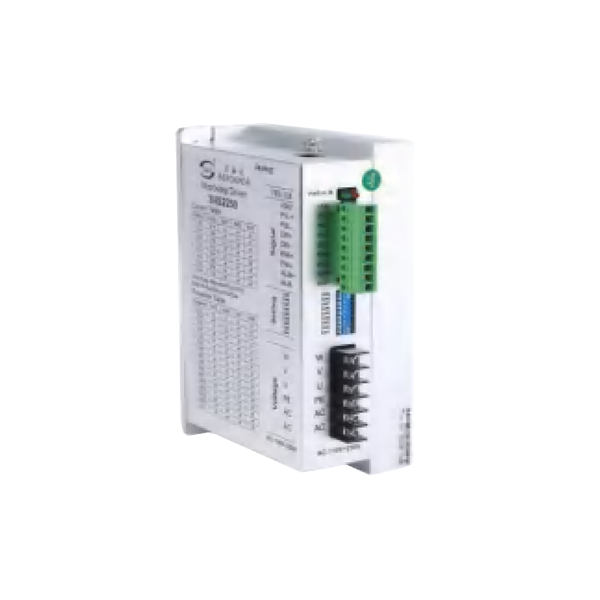
| Signal interface | PUL+ and PUL- are the positive and negative ends of the control pulse signal; DIR+ and DIR- are the positive and negative ends of the direction signal; ENA+ and ENA- are the positive and negative ends of the enable signal; ALM+ and ALM- are the positive and negative terminals of the alarm output signal; PLC control only needs to connect +24V, PUL-,DIR-,three lines |
| Motor interface | U, V, W corresponds the motor windings U, V, W, Arbitrarily swapping two of the three winding wires can change the direction of the motor, PE ground wire. |
| Power interface | The working voltage range is recommended for AC 110-230V. It is recommended to add a filter (EMI FILTER) before the power supply circuit. |
| LED | The driver has two indicators, red and green. The green light is the power indicator. The green light flashes after the driver is powered on. The red light is the fault indicator. The red light flickers when there is a fault in the gear and the encoder is misaligned. After the fault is cleared, the red light goes out. When an alarm occurs on the drive, it must be powered on again to clear the fault. |
| Installation Notes | Dimensions: 183*144*48 mm, mounting hole spacing156. installation should be close to the metal cabinet for better cooling |
| LED status | Drive status | |
|---|---|---|
| Green flashing | The driver is working properly (pulse input flashes faster) | |
| 1green、1red | Drive overcurrent | |
| 1 green、2 red | The code wheel is reversed or there is no code dial (you can change the parameter NO.15) | |
| 1 green、3 red | Position error (closed loop) | |
| 1 green、4 red | IPM Alarm | |
| 1 green、5 red | ADC hardware error | |

| Output current peak | Output current Rms | SW1 | SW2 | SW3 |
|---|---|---|---|---|
| 8.4A | depand by Pa5 parameter | on | on | on |
| 3.0A | 2.0A | off | on | on |
| 3.5A | 2.5A | on | off | on |
| 4.2A | 3.0A | off | off | on |
| 4.8A | 3.5A | on | on | off |
| 5.2A | 4.0A | off | on | off |
| 6.1A | 4.5A | on | off | off |
| 6.6A | 5.0A | off | off | off |
| Steps / Turn | SW5 | SW6 | SW7 | SW8 |
|---|---|---|---|---|
| 200 | on | on | on | on |
| 400 | off | on | on | on |
| 600 | on | off | on | on |
| 800 | off | off | on | on |
| 1000 | on | on | off | on |
| 1200 | off | on | off | on |
| 2000 | on | off | off | on |
| 3000 | off | off | off | on |
| 4000 | on | on | on | off |
| 5000 | off | on | on | off |
| 6000 | on | off | on | off |
| 10000 | off | off | on | off |
| 12000 | on | on | off | off |
| 20000 | off | on | off | off |
| 30000 | on | off | off | off |
| 8000 | off | off | off | off |