
Based on TI's new 32-bit multi-channel DSP processing chip platform, using internal PID current control algorithm design, with excellent performance. The built-in micro-segmentation technology and the automatic tuning function of the power-on parameter make the driver have the characteristics of low noise, low vibration low heat and high-speed high-moment output, and can be well adapted to most applications of stepping motors.
♦ Pulse mode: single pulse/CW/CCW pulse
♦ Signal level:5V-24V compatible
♦ Typical applications: stripping machine, marking machine, cutting machine, laser equipment, visual positioning, automatic equipment and so on. The application effect is particularly good in a device where the user desires high speed and small noise.
| Drive function | Operating Instructions |
|---|---|
| Microstep subdivision setting | SW5-SW8 four dial codes are used to select a total of 16 files of microsteps. When the user sets the subdivision, electric motion should be stopped first. For detailed microstep subdivision settings, please see the drive panel description. |
| Output current setting | SW1-SW3 three dial switches are used to select a total of 8 output currents. For the specific output current setting, please see the driver panel description. |
| Automatic half-flow function | SW4 is used to set the automatic half-flow function of the driver, off means that the quiescent current is set to half of the working current, and on means that the quiescent current is the same as the working current. In general use, SW should be set to off, so that the heating of the motor and the driver is reduced, and the reliability is improved. The current is automatically halved about 0.4s after the pulse train stops. |
| Signal interface | PUL+ and PUL- are the positive and negative ends of the control pulse signal; DIR+ and DIR- are the positive and negative ends of the direction signal; ENA+ and ENA- are the positive and negative ends of the enable signal. |
| Motor interface | A+ and A- are connected to the positive and negative terminals of the A-phase winding of the stepping motor; B+ and B- are connected to the positive and negative terminals of the B-phase winding of the stepping motor. When A, B two-phase windings are exchanged, the motor can be in the opposite direction. |
| Power interface | It is powered by AC/AD power supply. The working voltage range is recommended to be AC20~40V or DC24~50V. The power supply is greater than 100W |
| LED | The driver has two indicators, red and green. The green light is the power indicator. The green light flashes after the driver is powered on. The red light is the fault indicator. The red light flickers when there is a fault in the gear and the encoder is misaligned. After the fault is cleared, the red light goes out. When an alarm occurs on the drive, it must be powered on again to clear the fault. |
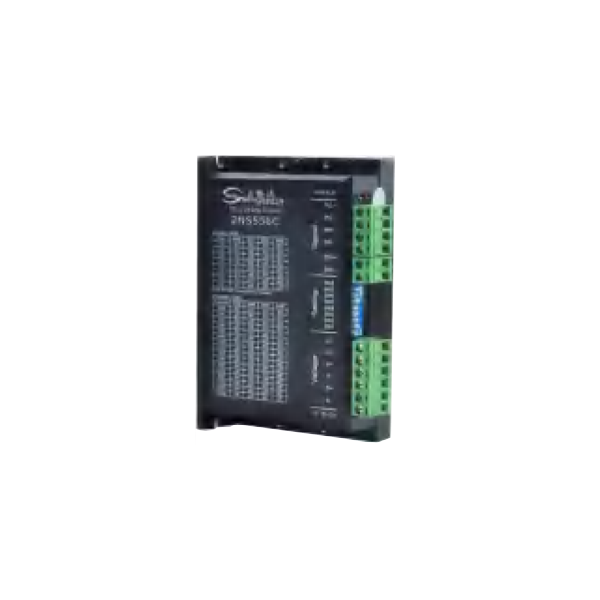
| Installation Notes | Dimensions: 118 * 76 * 28mm, mounting hole spacing112mm. Can be horizontal or vertical installation, advised to be vertical installation while it should be close to the metal cabinet for better cooling |
| LED status | Drive status | |
|---|---|---|
| Green light | Drive is not enabled | |
| Green flashing | The driver is working properly(Pulse flashing faster) | |
| 1green、1red | Drive overcurrent | |
| 1 green、2 red | Driver input voltage overvoltage | |
| 1 green、3 red | Drive internal voltage error | |

| Output current peak | Output current effective value | SW1 | SW2 | SW3 |
|---|---|---|---|---|
| 1.4A | 1.0A | on | on | on |
| 2.1A | 1.5A | off | on | on |
| 2.7A | 1.9A | on | off | on |
| 3.2A | 2.3A | off | off | on |
| 3.8A | 2.7A | on | on | off |
| 4.3A | 3.1A | off | on | off |
| 4.9A | 3.5A | on | off | off |
| 5.6A | 4.0A | off | off | off |
| Steps / Turn | SW5 | SW6 | SW7 | SW8 |
|---|---|---|---|---|
| 400 | on | on | on | on |
| 800 | off | on | on | on |
| 1600 | on | off | on | on |
| 3200 | off | off | on | on |
| 6400 | on | on | off | on |
| 12800 | off | on | off | on |
| 25600 | on | off | off | on |
| 51200 | off | off | off | on |
| 1000 | on | on | on | off |
| 2000 | off | on | on | off |
| 4000 | on | off | on | off |
| 5000 | off | off | on | off |
| 8000 | on | on | off | off |
| 10000 | off | on | off | off |
| 20000 | on | off | off | off |
| 40000 | off | off | off | off |